 Air leaving a compressor is hot, dirty, and wet—which can damage and shorten the life of downstream equipment, including valves, cylinders, and air tools. So before compressed air exits the system, it must be cleaned and lubricated. That’s where an FRL comes in! An FRL combines a filter, regulator, and lubricator into one component to keep air compressor systems in optimal working condition.
FRL Components
An FRL has three primary components:
- Airline filter
- Pressure regulator
- Lubricator
Each component has its role, supporting the larger air compressor system. We will explain more about these roles in the following sections.
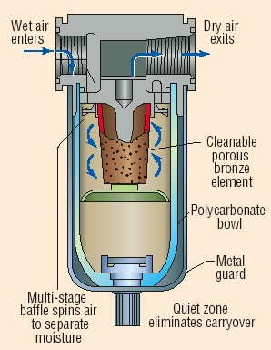
Airline Filter
An airline filter cleans compressed air. It strains the air, traps solid particles (dust, dirt, rust), and separates any liquids (water, oil) in the compressed air. Filters are installed in the airline upstream of regulators, lubricators, directional control valves, and air-driven devices such as cylinders and air motors.
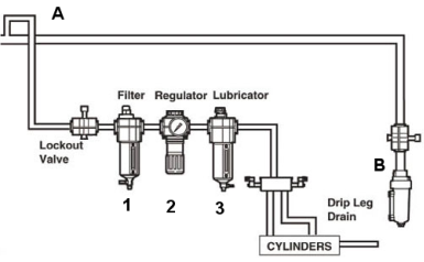
FRL System
Because airline filters remove contaminants from pneumatic systems, they prevent damage to equipment and reduce production losses due to contaminant-related downtime. Downtime is expensive and often results from a contaminated and poorly maintained compressed air system.
Selecting the proper filter size for any application should be done by identifying the maximum allowable pressure drop, caused by the filter. The pressure drop can be determined by referring to flow curves provided by the manufacturer.
Types of Air Filters
There are three common types of air filters:
- General-purpose
- Coalescing (oil removal)
- Vapor removal
General-purpose filters remove water and particles, coalescing filters remove oil, and vapor removal filters remove oil vapor and odor.
Pressure Regulators
Pressure regulators reduce and control air pressure in compressed air systems, including rotary screw air compressors. Regulators are also frequently referred to as PRVs (pressure-reducing valves).
Optimally, a pressure regulator maintains a constant output pressure regardless of variations in the input pressure and downstream flow requirements. In practice, the output pressure is influenced by variations in primary pressure and flow.
Pressure regulators are used to control pressure to:
- Air tools
- Blowguns
- Air gauging equipment
- Air cylinders
- Air bearings
- Air motors
- Spraying devices
- Fluidic systems
- Air logic valves
- Aerosol lubrication system
- Most other fluid power applications
General-purpose regulators are available in relieving or non-relieving types. Relieving regulators can be adjusted from high pressure to low pressure. Even in a dead-end situation, relieving regulators will allow the excess downstream pressure to be exhausted. This pressure relief causes a loud hissing sound which is perfectly normal.
Non-relieving regulators that are similarly adjusted will not allow the downstream pressure to escape. Instead, the trapped air will need to be released in some other way—for example, by operating a downstream valve.
Downstream equipment flow and pressure requirements must be determined to size the correct regulator for the application properly.
Lubricator
A lubricator adds controlled quantities of tool oil into a compressed air system to reduce the friction of moving components. Most air tools, cylinders, valves, air motors, and other air-driven equipment require lubrication to extend their useful life.
Using an airline lubricator solves the problems of too much or too little lubrication that arise with conventional lubrication methods such as a grease gun or oil. Airline lubricators also supply the right kind of lubricant for the tools used.
Once the lubricator is adjusted, the air-operated equipment is supplied with an accurately metered quantity of lubricant. The only maintenance required is a periodic refill of the lubricator reservoir.
Adding lubrication to a system also “washes away” compressor oils that travel through the system in vapor form. Mineral oils added to the system prevent synthetic compressor oil build-up on system components. When lubricators are not used in a system, a coalescing filter should be installed to remove compressor oil aerosols.
Downstream flow requirements determine the size of lubricators. Therefore, it's important to analyze airflow use and then choose a lubricator after deciding how much airflow is needed.
Types of Airline Lubricators
Airline lubricators come in one of two types:
- Oil-Fog
- Micro-Fog
Oil-Fog airline lubricators are used in simple, heavy-duty applications, such as single tools, cylinders, and valves. Micro-Fog lubricators are used for applications with more than one lubrication point, or several cylinders or valves.
In oil-fog lubricators, all the oil droplets visible in the sight dome are added directly into the airflow, which results in relatively large oil droplets passing downstream.
In micro-fog lubricators, the oil droplets visible in the sight dome are atomized and collected in the area above the oil in the bowl. The smaller, lighter particles are drawn into the airflow and pass downstream. As a result, only 10% of the visible oil drops in the sight dome are typically passed downstream.
Choosing The Right FRL For Compressed Air Systems
Compressed air is clean, readily available, and simple to use, but it can be the most expensive form of energy in your application if it is wasted. Unregulated or improper pressure settings can result in increased compressed air demand, which results in increased energy consumption.
Excessive pressure can also increase equipment wear, resulting in higher maintenance costs and shorter tool life. A rule of thumb states that every 2 psig increase in operating pressure adds 1% to compression energy cost.
Point-of-use FRLs (filter, regulator, and lubricators) are needed to ensure that every tool or process receives a clean, lubricated supply of compressed air at the proper pressure to provide peak performance.
The Ideal Filter For Compressed Air
Reliability is one of the most vital reasons to use compressed air, and proper filtration is the key to maximizing reliability and longevity. Unfortunately, compressed air can carry condensed water, oil carryover from compressors, solid impurities (pipe scale and rust) generated within the airlines, and other wear particles from the ambient air. These contaminants can cause problems at every point of use and should be removed by installing suitable filters.
Contaminant particle size is measured in micrometers (µm), representing one-millionth of a meter or 0.000039 of an inch. Filters are rated according to the minimum particle size that their elements will trap. For example, although filters rated at 40 to 60 µm are adequate for protecting most industrial applications, many point-of-use filters are rated at 5 µm. Note that finer ratings increase the pressure drop through the filter, equating to higher energy costs to compress the air.
For example, finer filters clog more rapidly, also increasing pressure drop. (In other words, while filters finer than necessary do not harm downstream components, they will negatively impact air system operating cost.)
Point-of-use filter
Many filter manufacturers will define the expected pressure loss and dirt holding capacity using curves related to pressure and flow. Therefore, particle-removal filters should be selected based on acceptable pressure drop and pipe-connection size.
A typical pressure drop through such filters would be between 1 and 5 psig. Therefore, a larger body size filter will produce less initial pressure loss and provide longer operating life than a smaller filter with the same removal ratings.
Most point-of-use filters claim to remove condensed water, typically via a cyclone separator at their inlet end. However, the water-removal efficiency of such filters is very dependent on the incoming air velocity. Therefore, these filters must match the intended airflow, rather than the acceptable pressure drop.
If the filter is intended to remove moisture, an automatic float-type drain should be provided to remove accumulated liquids from the filter bowl periodically. Generally, such filters have transparent polycarbonate bowls, which allow easy visual inspection of the sump level.
Numerous chemicals can attack this plastic material, and it only performs well at pressures below 150 psig and temperatures between 40° and 120° F. If the filter may be subjected to conditions beyond those limits, a metal bowl is required. A metal bowl is also needed if the filter is used with synthetic compressor lubricants, which often contain harmful chemicals to polycarbonate.
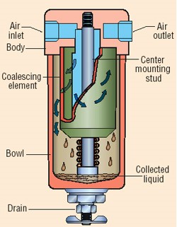
Coalescing filter
Coalescing Filters
Most of the oil and some condensed water in a compressed airstream will be in the form of mists or aerosols that can pass through the openings in standard airline filters. Air for instruments, spray painting, and bulk-material conveying frequently requires removing such droplets, and coalescing-type filters will accomplish this job.
Aerosol carryover through such filters is commonly stated as parts per million (ppm) of oil vs. air by weight and ranges from 1 to as little as 0.01 ppm. Coalescing filters are often rated to remove aerosols that are substantially smaller than the nominal size of the smallest solid particle that would be captured. Some models offer dual-stage filtration; the first removes solid particulates to protect the coalescing element in the second stage.
Because all coalescing filters create a more significant restriction to the airflow, pressure losses will be higher than those of conventional compressed air filters. Coalescing filters have an initial (or dry) pressure drop and working (or saturated) pressure drop based on pressure and flow rate. Therefore, the effective removal efficiency of such filters depends significantly on the air velocity passing through the filter assembly.
Choose a coalescing filter based on acceptable oil carryover, expected airflow rate, and pipe-connection size. For example, a coalescing filter rated at 0.1 ppm will typically have a clean, wetted pressure drop between 2 and 5 psig. A high-efficiency filter rated at 0.01 ppm can cause a reduction up to 10 psig once it becomes wet or fully saturated during service.
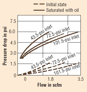
High-efficiency filter pressure by flow
Selecting The Right Pressure Regulators
Once a minimum suitable operating pressure is determined for any compressed air application, it is essential to supply the air at a constant pressure, regardless of upstream flow and pressure fluctuations. Thus, installing the proper regulator or pressure-reducing valve in the airline is critical.
Air regulators are special valves that reduce supply pressure to the level required for the efficient operation of downstream pneumatic equipment. A filter installed upstream will protect the regulator's internal passages from damage.
Poppet-Style Valves
There are several types of air regulators, and the simplest type uses an unbalanced-poppet-style valve. This design incorporates an adjustment spring, does not have a separate diaphragm chamber, and is non-relieving. Turning the adjustment screw compresses the spring, which forces the diaphragm to move, thus pushing a poppet to uncover an orifice.
As pressure rises downstream, it acts on the underside of the diaphragm, balancing against the force of the spring. The poppet throttles the orifice opening to restrict flow – and produce the desired downstream pressure. A spring under the poppet assures that the valve closes completely when no flow exists. This is the least expensive type air regulator.
Regulator with diaphragm chamber
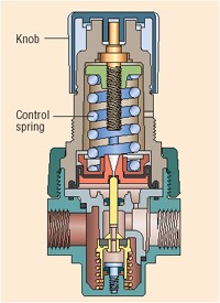
Diaphragm Chambers
Larger, more expensive regulators incorporate a separate diaphragm chamber with an aspirator tube exposed to the output pressure. Segregating the diaphragm from the primary airflow minimizes its abrasive effects and extends the valve’s life.
As flow through this regulator increases, the aspirator tube creates a slightly lower pressure in the diaphragm chamber. As a result, the diaphragm deflects downward and opens the orifice without significantly reducing the output pressure.
The effect is the same as increasing the adjustment setting. Thus, this style regulator has a minimal drop (output pressure decay) as supply pressure varies. The table below compares how that variance occurs with a small and a large diaphragm.
The larger diaphragms in these regulators improve response and sensitivity. However, as discharge flow through the regulator increases over its entire range, output pressure drops. Thus, setting the regulator’s desired output pressure must be done under typical flow conditions.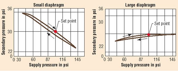
Supply pressure in small vs. large diaphragms
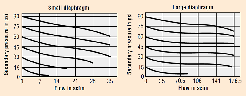
Flow in scfm of small vs. large diaphragms
Balanced Poppet & Precision Regulators
Another type of regulator incorporates a balanced poppet, but otherwise has the same general construction as the separate diaphragm version. It has a significantly larger orifice to allow for greater airflow. The poppet is pressure-balanced to maintain good stability. Thus, the effects of output pressure fluctuations cancel out, which improves sensitivity and response, and reduces droop.
Finally, precision regulators often employ several isolated diaphragms acting against flapper valves and nozzles in a balancing principle and are normally manufactured in limited flow capacities with smaller connection ports.
Considerations When Selecting Regulators
Selecting the best type of regulator for a specific application first requires choosing among these styles. Mini-regulators are commonly the direct-acting, non-relieving type, while most standard regulators fall within the self-relieving, separate-diaphragm-chamber style.
The next consideration becomes primary (unregulated supply) pressure versus desired secondary (output) pressure.
Finally, the desired airflow rate must be selected. Adjusting screws are available in two styles: a tamper-resistant, locking Tee type or a push-lock, plastic knob type. The first is best when a fixed operating pressure will be set once and left alone.
However, the adjustable knob style (quite common on modular FRLs) is the correct choice for general use, where operating pressure can be adjusted without tools. Regulators also are defined by body size (orifice flow rating) and connection size.
Although several models may appear acceptable for any given airflow and pressure, a larger body size regulator will produce better setting sensitivity and less droop than a smaller body model under the same set of operating conditions.
An output pressure gauge is essential, although many manufacturers frequently offer it only as an option. Mounting brackets are another useful option.
Choosing The Best Airline Lubricator
Airline lubricator
Many pneumatic system components and pneumatic tools perform better when lubricated with oil. Injecting an oil mist into the airstream can continuously lubricate valves, cylinders, and air motors for proper operation and long service life.
Locating the lubricator last in the pipeline is important to ensure that the correct amount of lubrication reaches each device. Too little oil can allow excessive wear and cause premature failure. On the other hand, excessive oil in the pipeline is wasteful and can contaminate the surrounding area when the air exhaust carries oil out of the tools and valves.
Intermittent lubrication may be the worst condition of all because the oil film can dry out and form sludge or varnish on the internal surfaces of the equipment.
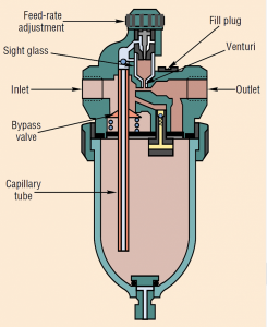
Airline lubricators meter oil from a reservoir into the moving airstream; as high-velocity air passes through a venturi, it draws the oil up and through a capillary, then drips it into the airstream.
The moving air breaks up the oil into a mist (small droplets) or fog (larger droplets) and carries it downstream into the air-powered device. In a typical lubricator, all the air passes through the venturi during low-flow conditions.
Under higher flow conditions, a spring-loaded bypass valve opens to direct the excess flow around the venturi to a point downstream where it rejoins the lubricated flow. A manual adjusting valve sets the oil drip rate, and a sight glass enables the operator to monitor the output. A fill plug provides access to refill the reservoir, often made from polycarbonate. The same precautions about polycarbonate apply to lubricators as they do to airline filters.
Lubricator pressure and flow
Lubricators typically have a larger flow range than an equivalent size regulator or filter, but their pressure drop increases quite rapidly as flow increases.
The standard acceptable pressure loss for a lubricator is 3 to 7 psig. Lubricators are generally selected based on pipe connection size, oil reservoir capacity, and allowable pressure loss versus flow rate. Many manufacturers publish a minimum flow rate for the venturi to function properly.
Remember to account for this added downstream pressure loss when setting the pressure regulator. Set it at desired use pressure plus lubricator loss (drop).
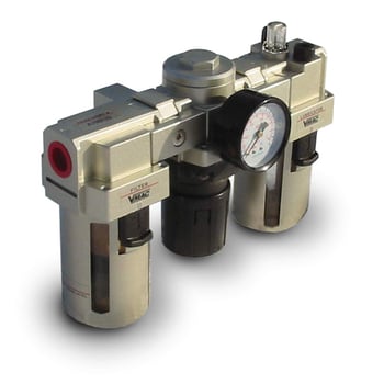
Modular & Combination FRL Units
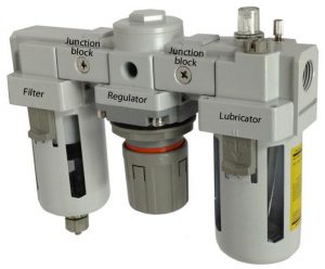
Combination FRL unit
Manufacturers frequently preassemble filters, regulators, and lubricators to form combination units. They are packaged together as standard body sizes with common connection port sizes. Interconnections may be via threaded nipples or modular face connectors.
The modular connectors allow easy removal of components for servicing or cleaning. In addition, some manufacturers combine filters and regulators in stacked assemblies where the filter head becomes the regulator body. The components share common inlet and outlet connections, making the assembly very compact.
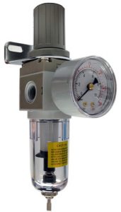
Individual pressure regulator
Packaged combination units are practical for most industrial applications, whether FR only or complete FRL. The selection criteria are similar to the individual components, except that only the combined pressure and flow performance are considered.
When critical requirements dictate the use of specialty filters or precision regulators, the assembly must be made up of individual selections and connected with pipe nipples.