
Proper sizing is crucial for every component of your air compressor system, especially the hoses, as the size of your air hose directly impacts airflow and overall efficiency. No matter how powerful your compressor is, restricting airflow at any point in the system can lead to poor performance, increased wear, and higher energy costs over time. By ensuring your air hoses are appropriately sized, you’ll maximize efficiency, reduce energy waste, and extend the life of your compressor—saving you money and frustration in the long run.
Air travels from the compressor head to your tool through components such as hoses, fittings, valves, and tanks. Each component restricts the flow of air in some way, depending on the geometry of the component and the magnitude of the flow passing through it.
For example, a 100-foot, 1” hose delivering 100 CFM at 90 psi will result in a 3.35 psi pressure drop. If that same hose is tripled to 300 feet, the pressure drop is 10.1 psi, which means the air is now pressurized to only 80 psi.
As a result, your compressor is working harder and is using more power than it should to keep up with your air demand, or—if it can’t keep up—your tool performance will suffer. In some cases, where power at the tool is essential, you may be unable to complete your work.
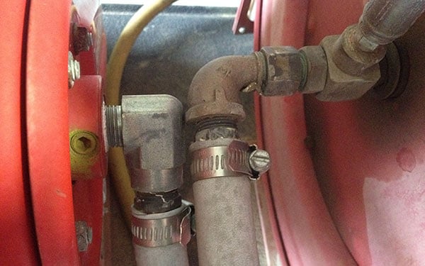
90° fittings like this may restrict airflow
How Fittings Cause Pressure Drops
Pressure drops occur when airflow is restricted by pipes or fittings. Imagine trying to breathe through a drinking straw—it’s much harder to get a large volume of air through that small opening. The reason? The smaller the diameter, the faster the air must move to maintain the same airflow.
This increased velocity creates more friction as air moves along the walls of the pipe or fitting, leading to greater losses. In pipes and hoses, the length of the pipe adds to these losses. When calculating pressure drops, always account for the reduced diameter caused by fittings, as they can significantly impact performance.
You might be surprised by how narrow the actual flow area is inside some fittings—quick-connect fittings are notorious for this. Before choosing one, take a closer look at the internal diameter and double-check the specifications to ensure it won’t restrict your system’s airflow.
Calculating Pressure Drop of Fittings
You can use quick calculators or charts like those found at Engineering Toolbox, to calculate the pressure drop in your pipes or components.
Note that this calculator is for hard pipe, which is a well-defined shape. Flexible hose typically contains many bends and loops, so creating an accurate calculator is impossible. Although flexible hose will have more losses than a pipe with an identical inside diameter, we can still use the pipe loss calculation to get a decent estimate and see the influence diameter has on pressure loss.
When sizing your air compressor, consider each of the following components that can cause pressure loss:
- Hose reels
- System piping/tubing
- Filters
- Regulators
- Lubricators
- Fittings
Components such as filters will often have specified operating pressure ranges, so check the documentation and specifications carefully to match components to the system.
When considering fittings and quick connects, work with your suppliers to ensure they are rated for the maximum pressure your compressor system is rated for, so they do not cause excessive pressure drop at the required flow rates.
Pressure Drop Sizing Examples
To illustrate the dramatic difference that pipe or hose diameter makes on pressure loss, we used the pressure drop calculator tool to compare 100 ft long pipes with internal diameters of ½”, ¾”, and 1”.
In this example, we have 70 CFM of compressed air, delivered at 100 psi gauge pressure (equivalent to 114.7 psi absolute pressure*) at the upstream hose entrance.
The approximate pressure loss from end to end for the three pipe sizes is:
- 1″ x 100’ = ~1.4 PSI pressure loss
- 3/4″ x 100’ = ~5.7 PSI pressure loss
- 1/2″ x 100’ = ~44 PSI pressure loss
Your compressor would have to operate at a constant ~134 psi gauge pressure† to maintain 100 psi at the tool with the ½” pipe.
Increasing Pressure vs. Increasing Supply Line Size
Increasing the pressure of your compressor to compensate for flow losses can dramatically impact how hard your air compressor system needs to work. Meanwhile, increasing the size of the supply lines can provide the following benefits:
- Less fuel/energy used by your compressor
- Less heat generated by the compressor
- Longer oil life and service interval
- Lower noise output from the compressor
- Improved safety due to lower operating pressures and lower temperatures
- Lower load on drive system components
- Less wear and longer life of your compressor
Each restrictive fitting, hose, accessory, and bend added to your system results in cumulative pressure drop and can negatively affect the performance of your tool or equipment. Recognizing this and planning and sourcing the right-sized components will enable your air system to perform better.
Keep in mind that formulas and calculators like the one used above are just a guide. Real-life scenarios depend on many factors, each affecting your results. Using a larger diameter hose may cost more, but it can result in long-term savings and may even allow for a lower pressure or output compressor, saving money upfront.

*Absolute pressure is the pressure relative to a perfect vacuum. Gauge pressure is relative to atmospheric pressure. Standard atmospheric pressure is 14.7 PSI, so for a calculation such as this one, which requires absolute pressure, atmospheric pressure (14.7 psi) needs to be added to your gauge pressure.
† It might seem logical to assume that the inlet pressure would need to rise by the same amount as the pressure loss calculated in the pipe. However, the required increase is slightly less. As pressure rises, the volume flow and flow velocity decrease (for the same mass of air), which in turn reduces the pressure drop. This dynamic means that the relationship between pressure and airflow isn’t linear, resulting in a more moderate pressure increase than expected.
