
So, you’ve decided you are in the market for an air compressor to add to your existing industrial engine or to include as part of a new piece of equipment you are designing.
Maybe you or your customers are tired of having to haul another separate piece of equipment around to job sites, or maybe you’re looking to open up new markets with a product that does it all. In any case, you are going to have to figure out what your needs are so you can start looking for the right piece of equipment.
To get started you need to consider the following:
- What tools would you like to use?
- What are their air requirements?
- What duty cycle will they be used at?
- How will your air requirements vary depending on the job at hand?
- Will you be using an air receiver tank and what is the tank volume?
- Are you willing to wait for the air pressure to build between tool use?
- What other loads are going to be imposed on the engine?
- Will these other loads be running concurrently with air compressor use?
How To Determine Your Tools’ Air Requirements
Each air tool should have a published air requirement specification. Often this is included in the owner’s manual or documentation that came with the tool and is typically stated in airflow (CFM – cubic feet per minute) at a specific pressure. Many air tools are designed to operate in the 90-130 psi range which is a requirement that almost all air compressors can meet.
Where it can get a little interesting is when looking at the airflow specification. Commonly this is stated as an “average airflow consumption” but this can be misleading as it assumes you will only be using the tool intermittently.
Some tools will specify both an average and actual consumption. For example, a popular ½” impact gun states a 4.2 CFM average air consumption and 22CFM during actual use. A quick calculation shows us that this particular tool manufacturer has assumed that this tool will typically only be used an average of 20% of the time.
The amount of time a tool is used is referred to as duty cycle and, in the small air tool industry, it’s commonly based on a cycle time of a minute. Therefore, a 25% duty cycle would refer to using a tool for 15 seconds out of a minute.
For larger or specialized tools, the duty cycle may be quite different. A pneumatic angle grinder or sander might consume 18 CFM under load and be used continuously for five minutes and then put aside for an hour. While this works out to only an 8% duty cycle, because of the longer on time it would require a larger compressor or larger air receiver tank (more on this later) than the impact gun mentioned above.
If possible, find out the actual air requirements for everything you want to power with compressed air and apply the duty cycle that you will actually use each for. It will make the selection of your compressed air system more accurate.
How To Figure Out Everyday Air Needs
Once you have an idea what the air requirements are for each tool and piece of equipment, you need to determine how these air needs might overlap during a typical day. This is an important factor to consider as it has a major impact on the size and type of the compressor and requirements of an air receiver tank.
For example, if the compressor system is part of a mechanic’s service truck, it might only be used to power one tool at a time at a duty cycle of 10-30% in a time span of a minute or two a few times per hour. Contrast this with a compressor system used for the application of spray foam insulation where there are multiple operators each with a spray guns operating at a duty cycle of 60-90% in a time span of an hour.
Do You Need An Air Receiver Tank?
The next important thing to consider is the use and size of an air receiver tank. A receiver tank stores compressed air and acts as a buffer between compressor output and surges in air demand due to heavy tool use.
An appropriately sized tank will allow the compressor to run at its designed duty cycle while still allowing the system to provide a steady supply of air. A larger tank will typically allow a higher intermittent air consumption with a smaller compressor as long as the compressor’s rated duty cycle is not exceeded. In other words, the time to fill the tank from cut-in to cut-out pressure doesn’t overheat the compressor. The duty-cycle and rated maximum run time should be provided by each compressor manufacturer.
Although the rule of thumb of four gallons per HP is sometimes used, it makes many assumptions that may not reflect your particular situation. Instead, use this simple equation to determine the minimum recommended size of your air receiver tank if your demand is occasionally more than the compressor can continuously output. Note this assumes you will not exceed your compressor’s duty cycle when refilling the receiver tank.
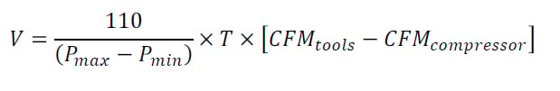
Where:
V=required minimum receiver tank volume ( US gallons)
Pmax = Compressor cut-out pressure (PSI)
Pmin = Compressor cut-in pressure (PSI)
CFMtools = Max total air consumption possible at one time (CFM)
CFMcompressor = continuous output of the compressor (CFM)
T = Length of time high air consumption will be in demand (minutes)
This equation can be used to find a balance between compressor output and tank size that best suits your needs, for example if you occasionally require 45 CFM at a minimum pressure of 90 psi for one minute out of every 10 minutes, you could meet this need with a compressor that can output 45 CFM and not require a receiver tank at all, or you could use a compressor that outputs only 10 CFM coupled with a 100-gallon tank with a cut-out pressure of 130 PSI.
Properly sizing a receiver tank and air distribution system is beyond the scope of this article, but you can learn more in our How To Size An Air Receiver Tank blog.
How To Determine Your Power Requirements
Now you have an idea what your air consumption needs are and have decided on a compressor size and receiver tank. The next step is to determine the power requirements of running the compressor, commonly specified as CFM per HP.
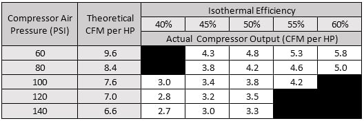
An important factor in determining a compressor’s CFM/HP ratio is its thermal efficiency. This is fundamentally a measure of how efficient the compressor can turn the engine power into compressed air. There are many factors that influence the isothermal efficiency of an air compressor; compressor type (i.e. piston vs rotary screw or multiple vs single stage compression), discharge pressure, cooling method, etc.
Each compressor manufacturer should be able to supply a CFM/HP curve at different pressures but if not the following table shows how actual output can vary with pressure and isothermal efficiency.
If this information is not available, we can approximate a typical compressor’s performance using the following table at about 3-4 CFM per HP:
Now that you have a ballpark power requirement for compressor operation, you need to add in the other loads to arrive at a total load demand on the engine.
Engine manufacturers will commonly specify a gross and net rated power. Gross power refers to the engine power without any loads (i.e. no water pump, alternator, oil pump, or cooling fan), a situation that you will typically never experience. The Net power rating is the one to use but you may still need to factor in the power required to run the cooling fan and alternator.
You will want to work with your engine supplier to determine what has been accounted for in the net power rating specification.
Torque Curves Under Operating Conditions
Once you have some engines to consider, you can look at comparing the torque curves under the operating conditions you will be running at.
A typical industrial engine has a hill-shaped curve with a peak somewhere is the upper-middle rpm range while a compressor’s drive torque curve at a particular operating pressure can be almost flat or slightly U shaped.
These curves should be plotted to compare the engine’s ability to drive the compressor (and any other concurrent loads) at different operating RPMs. You are going to want to source an engine that can provide the torque you require with some reserve as a safety margin for situations where the engine is not able to produce rated power. A basic graph showing this comparison is shown below.
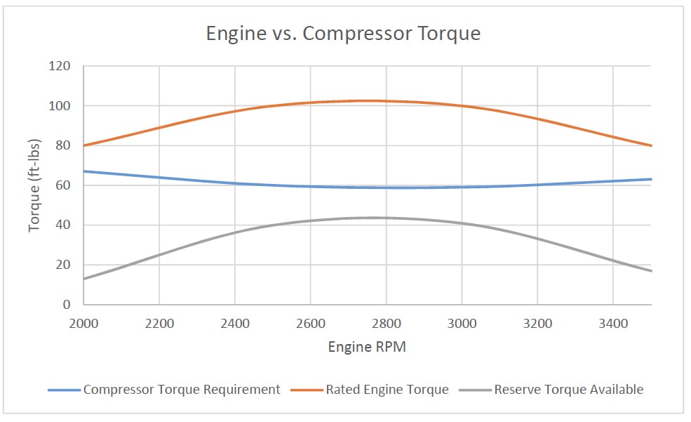
Some factors that may reduce the available power include: low-quality fuel, extreme high or low ambient temperatures, high altitude, turbo or charge air cooler not working properly, clogged air filter, exhaust restrictions, or simply an engine that is worn out or in need of servicing.
Your engine supplier should be able to provide you with conversion tables to help calculate some of these effects which can lower the engine’s torque by 30 % or more.
Similar factors also apply to the compressor drive torque and should be discussed with your compressor manufacturer to ensure that, even under the worst-case scenario, there is still enough torque available to meet the demand of the compressor.

There are many factors to consider when sourcing an appropriate engine to power your compressor. Hopefully, this article has helped prepare you to be able to better discuss your options with your chosen engine and compressor supplier.
